DYEMANSION POWERSHOT C Spray Booth Cleaning Powder-Based Plastic Components 17201
Item ID: 21849
Condition: Used
Stock: Only ${ $store.getters['21849/currentItemVariation'].stock.net } in stock
The item is already sold
* Excl. VAT excl. Shipping
DYEMANSION POWERSHOT C
Here we offer you a Dyemansion Powershot C blasting cabin.
Gentle cleaning of powder-based plastic components
DYEMANSION POWERSHOT C
DEPOWDERING
STRUCTURE AND FUNCTION:
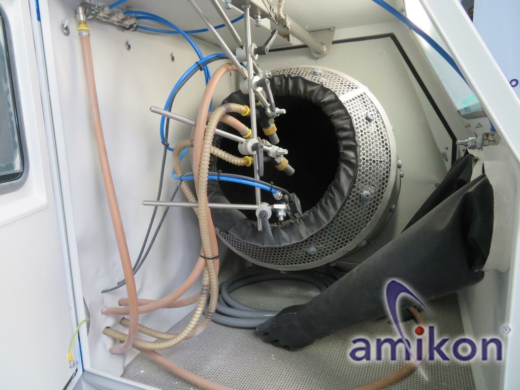
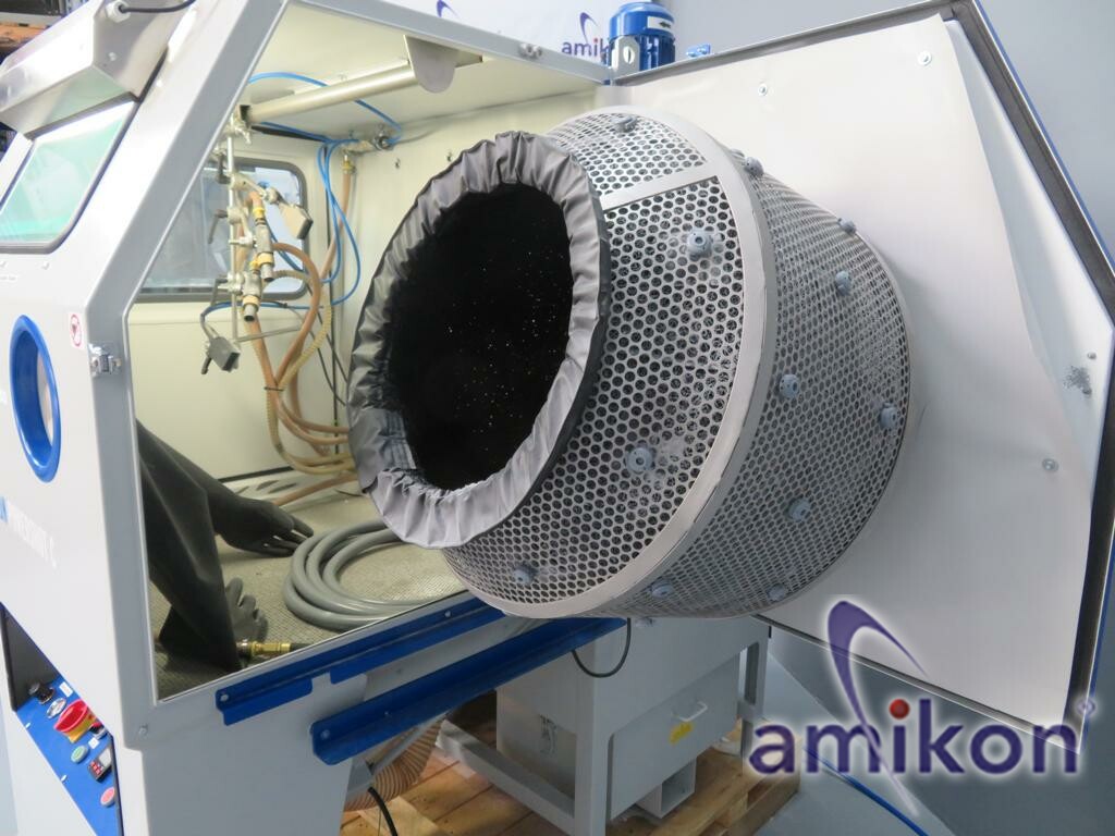
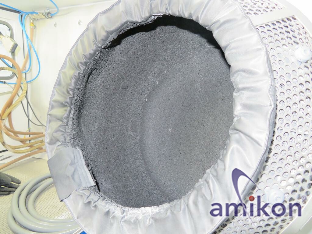
Blasting cabin:
The blasting cabin contains the following components:
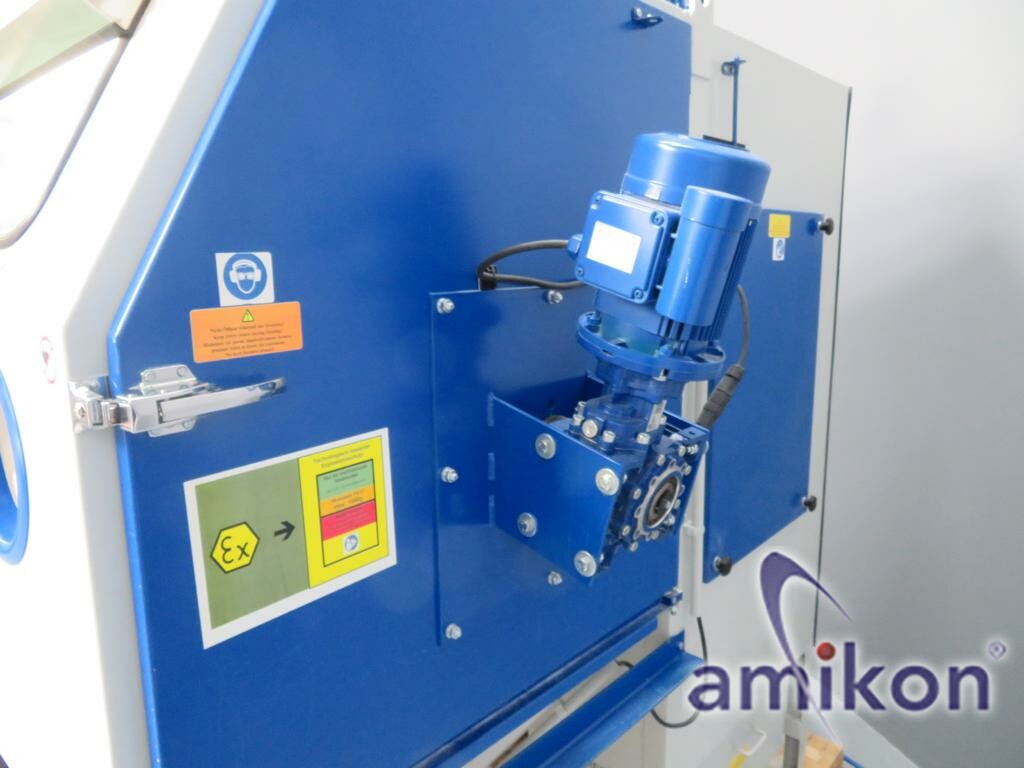
Blasting basket for holding the parts.
The blasting basket is driven by a gear motor and rotates during the blasting process at approx. 3.6 rpm.
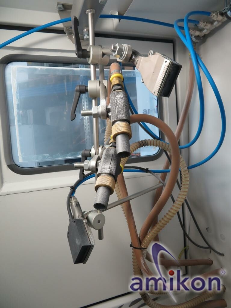
Blasting nozzles:
Two blasting nozzles.
The blasting nozzles are supplied with adjustable air pressure.
They draw the blasting medium through the dosing valves from the cyclone and create a defined air / blasting medium mixture.
The blasting nozzles focus the air / blasting medium mixture, which removes excess powder from the additive manufacturing process.
Multijet flat jet nozzle:
Two blow-off nozzles (Multijet flat jet nozzles) with ionizers.
They create a linear air curtain, with which they blow off dust, blasting medium, or surface contaminants
from the components and the blasting basket.
The ionizers minimize static charges of the generated dust and ensure a safe,
even flow of the air / blasting medium mixture.
Laval nozzle:
2 VA-Laval blow-off nozzles.
These nozzles are mounted outside the blasting basket.
They create a wide air cone and keep the blasting cabin dust-free.
Air hose in blasting cabin:
In the cabin, there is an air hose for cleaning the interior of the cabin as well as for blowing off components during manual blasting.
The air hose is constantly under pressure. When the black plastic tip is bent, a compressed air jet escapes.
Fan motor:
The fan motor is mounted on the cabin roof above the filter chamber.
The fan motor draws air through the cartridge filter and thus creates negative pressure in the filter chamber.
On the pressure side of the fan motor, the airflow is divided.
One part flows out of the machine through the exhaust port, the other part is returned to the blasting cabin.
The division of the two parts is controlled with the negative pressure throttle valve.
Blasting medium – recovery system (cyclone):
Cyclone
The negative pressure generated by the fan motor in the filter chamber drives the material flow in the cyclone.
The air/dust/blasting medium mixture flows from the blasting cabin into the cyclone through the horizontal hose, which is generated by the blasting process.
In the cyclone, these substances are separated from each other:
The air/dust mixture leaves the cyclone through the vertical hose upwards and is directed into the filter chamber.
There, the dust is separated.
The blasting medium falls down. A sieve retains coarse impurities.
The cleaned blasting medium collects in the funnel for reuse in the blasting medium circuit.
Dosing valve:
Dosing valve of the blasting nozzles
The dosing valve returns the blasting medium collected in the cyclone to the blasting nozzles.
The dosing valve enriches the blasting medium with air to improve flowability.
Cartridge filter with dust bucket
Filter chamber with cartridge filter
The cartridge filter is located in the filter chamber.
It separates the dust from the air/dust mixture coming from the cyclone.
The dust collects on the outside of the cartridge filter.
The dust is removed from the filter cartridge by regular air pulses (time interval approx. 40 – 60 sec, duration approx. 500 ms)
and falls into the dust bucket.
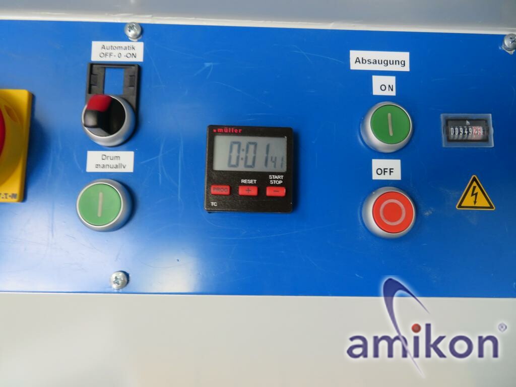
Control console:
1 pressure control valve for setting the inlet air pressure of the blasting nozzles
2 manometers for displaying the blasting pressure (inlet air pressure of the blasting nozzles)
3 emergency stop switch
4 rotary switch automatic operation switch positions (OFF – 0 – ON)
5 manual button drum drive on/off
6 timer for setting the blasting duration
7 button main switch on (operation)
8 button main switch off (standby)
9 operating hours counter
Technical data:
Dimensions width 915 mm, length 1665 mm, height 2030 mm
Space requirement:
Minimum space required for operating the Powershot C blasting cabin:
Length 2465 mm, width 2915 mm, height 2300 mm
Product data
Connection power 0.75 kW
Weight 480 kg
Connections:
Electricity voltage 3x400 V, frequency 50 Hz, rated current 2.5 A; plug connection CEE16A, clockwise rotation.
The pneumatic connection is located below the cyclone.
Compressed air:
Hose sleeve, internal cone – external thread G1/2“ hose inner diameter 19 mm, PN 16 bar compressed air water and oil-free
Inlet air pressure minimum 6 bar inlet air pressure maximum 7 bar
Compressed air consumption
Minimum blasting pressure: 1.4 m3/min at 2.5 bar Maximum blasting pressure: 2.5 m3/min at 7 bar
Type: POWERSHOT C PULSAR III S 17201
Condition: used
Scope of delivery: (See image)
(Changes and errors in the technical data, specifications are reserved!)
We would be happy to answer any further questions by phone.
| Technical characteristic | Value |
|---|---|
| Item ID | 21849 |
| Condition | Used |
| Model | POWERSHOT C PULSAR III S |
| Manufacturer | DYEMANSION |
| Content | 1 piece |
| Weight | 500000 g |
EU Responsible Person
DyeMansion GmbH
Robert-Koch-Straße 1
82152 Planegg-München
Germany
hello@dyemansion.com
+49 89 4141705 00
Manufacturer details
DYEMANSION
DyeMansion Inc.
USA
3D Lasersinter
Vanguard Si12 Basic Model / Upgrade 2017 Laser Sintering System
EUR 58,000.00 *
The item is in stock
* Excl. VAT
excl.
Shipping
Stratasys Fortus 450mc Industrial 3D Printer + CLEAN MATIC 3150 + Transformer – Complete System
EUR 29,500.00 *
The item is in stock
* Excl. VAT
excl.
Shipping
Top item
SLM Solutions – Selective Laser Melting Machine SLM 280 HL 3D Printer with plenty of accessories
EUR 80,000.00 *
The item is in stock
* Excl. VAT
excl.
Shipping
EOS Formiga P 100 Laser Sinter System
EUR 37,000.00 *
The item is in stock
* Excl. VAT
excl.
Shipping
Renishaw AM250 metal 3D printer and the associated SMC Thermo Chiller HRS024-A-20-T (MS400)
EUR 36,500.00 *
The item is in stock
* Excl. VAT
excl.
Shipping
EOS P 390 – Industrial 3D Printer (Laser Sintering System, SLS Laser)
EUR 38,000.00 *
The item is in stock
* Excl. VAT
excl.
Shipping
ProX™ 800 3D Production Printer von 3D Systems – Hochleistungs-SLA-Drucker
EUR 105,000.00 *
The item is in stock
* Excl. VAT
excl.
Shipping
EOS P 396 | PSW 3.8 – Industrial 3D Printer (Laser Sintering System, SLS, CO₂ Laser)
EUR 98,000.00 *
The item is in stock
* Excl. VAT
excl.
Shipping
Stratasys OBJET350 Connex3 3D printer and cleaning + glovebox + PC
EUR 10,000.00 *
The item is in stock
* Excl. VAT
excl.
Shipping
3DGENCE Industry F420 3D Printer + Interchangeable Nozzle Head
EUR 22,000.00 *
The item is in stock
* Excl. VAT
excl.
Shipping
Stratasys Objet 260 Connex 2 3D Printer and Cleaning Glovebox
EUR 19,500.00 *
The item is in stock
* Excl. VAT
excl.
Shipping
Top item
SLM Solutions Selective Laser Melting Machine 3D Printer SLM 500+ Accessories
EUR 615,000.00 *
The item is in stock
* Excl. VAT
excl.
Shipping
Trumpf TruPrint 3000 G02 Laser Metal Fusion Medium Format 3D Printer
EUR 85,000.00 *
The item is in stock
* Excl. VAT
excl.
Shipping
Markforged X7 Gen 2 FDM FFF 3D Printer
EUR 29,000.00 *
The item is in stock
* Excl. VAT
excl.
Shipping
German RepRap (innovatiq) X500 3D Printer
EUR 10,000.00 *
The item is in stock
* Excl. VAT
excl.
Shipping
